Serial and Smart Serial Back to Back
Serial and Smart Serial Back to Back
I have built a small collection of hardware and software for exploring X.25 networking. It contains routers, interfaces and bridges from the 1990s through to the early 2020s.
Welcome to my Lab has an introduction to the various devices discussed below.
The Problem
If we want to connect two routers back to back using Smart Serial or LFH-60 connectors, do we need a CSU/DSU?
Cisco’s Understanding the 2-Port Serial WAN Interface Card (WIC-2T) page says that the WIC-1T and WIC-2T do not have on board CSU/DSU:
Note: There are no framing, clocking or linecode parameters or commands being used here. This is because this card does not have an integrated channel service unit/data service unit (CSU/DSU). You need to use an external CSU/DSU.
A CSU/DSU (channel service unit/data service unit) is similar to a modem for a WAN, for example to connect it to ISDN. Serial cards don’t need them, right?
Goals
- Connect two routers back to back over serial.
- Establish X.25 connectivity between them.
- Demonstrate X.25 over TCP (XOT) connectivity.
- Demonstrate IP over X.25 connectivity.
Connect two routers back to back over serial
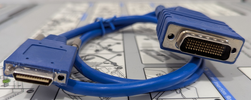 LFH-60 to Smart Serial Cable
I ordered a “CAB-SS-2660X-03” DTE cable, but I’m sure it’s an after market cable because of the bag and lack of logos. It says “703-4266” on both the plug and the bag.
I believe that “CAB-SS-2660X-03” breaks down as:
- CAB: Cable.
- SS-: Smart Serial (on one end).
- 26: The Smart Serial male plug is DTE.
- 60: The LFH-60 male plug is DCE.
- X: Crossover.
- -03: 3 feet long.
Which would make “CAB-SS-6026X”:
- CAB: Cable.
- SS-: Smart Serial (on one end).
- 60: The LFH-60 male plug is DTE.
- 26: The Smart Serial male plug is DCE.
- X: Crossover.
This matters because the clock lines are wired to different pins on the LFH-60 end for DTE versus DCE (Cisco DB-60 to DB-60).
Initial 3845 (NM-4T LFH-60) Config
I configure the LFH-60 end as DTE:
interface Serial2/0
 bandwidth 1948
 no ip address
 encapsulation x25
 x25 win 7
 x25 wout 7
 x25 ips 1024
 x25 ops 1024
Initial 2610 (WIC-2T SS) Config
Then I configure the Smart Serial end as DCE:
interface Serial0/0
 bandwidth 1948
 no ip address
 encapsulation x25 dce
 x25 win 7
 x25 wout 7
 x25 ips 1024
 x25 ops 1024
Diagnostics
With both debug x25 events and debug serial interface enabled and terminal monitor running on both consoles, I plug in the cable:
c3845#
Apr 6 00:56:13.592: %LINK-3-UPDOWN: Interface Serial2/0, changed state to up
Apr 6 00:56:13.592: Serial2/0: X.25 O R/Inactive Restart (5) 8 lci 0
Apr 6 00:56:13.592: Cause 0, Diag 0 (DTE originated/No additional information)
Apr 6 00:56:13.592: Serial2/0: X.25 I R2 Restart (5) 8 lci 0
Apr 6 00:56:13.592: Cause 7, Diag 0 (Network operational/No additional information)
Apr 6 00:56:14.592: %LINEPROTO-5-UPDOWN: Line protocol on Interface Serial2/0, changed state to up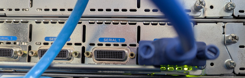 LFH-60 plugged into NM-4T
Apr 6 00:56:11.911: PowerQUICC(0/0): DCD is up.
Apr 6 00:56:13.589: Serial0/0: X.25 O R/Inactive Restart (5) 8 lci 0
Apr 6 00:56:13.589: Cause 7, Diag 0 (Network operational/No additional information)
Apr 6 00:56:13.589: Serial0/0: X.25 I R3 Restart (5) 8 lci 0
Apr 6 00:56:13.589: Cause 0, Diag 0 (DTE originated/No additional information)
Apr 6 00:56:13.706: %LINK-3-UPDOWN: Interface Serial0/0, changed state to up
Apr 6 00:56:14.707: %LINEPROTO-5-UPDOWN: Line protocol on Interface Serial0/0, changed state to up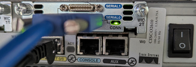 Smart Serial plugged into WIC-2T
Excellent, both ends can see the other.
Establish X.25 connectivity between the routers
I already have the following in my config on both ends, which enables XOT (X.25 over TCP) connections in to the routers:
x25 profile default dxe
 x25 address 702001
 x25 win 7
 x25 wout 7
 x25 ips 2048
 x25 ops 2048

x25 routing

line vty 5 30
 transport input pad
On IOS 15 we need to grant incoming XOT connections access, otherwise they are rejected:
xot access-group 10 profile default
access-list 10 permit any
From previous configuration, the 3845 is already using addresses in the 703… range and the 2610 is using addresses in the 702… range. I assign new addresses to the new serial interfaces.
c3845(config)# interface Serial2/0
c3845(config-if)# x25 address 703200
c3845(config-if)# exit
c3845(config)# x25 route 7022.* interface Serial2/0
c2610(config)# interface Serial0/0
c2610(config-if)# x25 address 702200
c2610(config-if)# exit
c2610(config)#x25 route 7032.* interface Serial0/0Test X.25 PAD connection from 2610 to 3845
To test connectivity I connect from the 2610 to the 3845 and vice versa using the pad command:
c2610# pad 703200
Trying 703200...Open

c3845.lan on line 711.

C i s c o  S y s t e m s
      ||        ||
      ||        ||
     ||||      ||||
 ..:||||||:..:||||||:..

User Access Verification

Username:
Password:

c3845>
Which produced these debug logs:
Apr  6 01:17:01.385: Serial0/0: X.25 O R1 Call (15) 8 lci 1
Apr  6 01:17:01.385:   From (6): 702200 To (6): 703200
Apr  6 01:17:01.385:   Facilities: (0)
Apr  6 01:17:01.385:   Call User Data (4): 0x01000000 (pad)
Apr  6 01:17:01.389: Serial0/0: X.25 I R1 Call Confirm (3) 8 lci 1
Apr 6 01:17:01.392: Serial2/0: X.25 I R1 Call (15) 8 lci 1
Apr 6 01:17:01.392: From (6): 702200 To (6): 703200
Apr 6 01:17:01.392: Facilities: (0)
Apr 6 01:17:01.392: Call User Data (4): 0x01000000 (pad)
Apr 6 01:17:01.392: Serial2/0: X.25 O R1 Call Confirm (3) 8 lci 1Demonstrate X.25 over TCP (XOT) connectivity
Using xotpad I can now connect through the 3845 to the 2610 over XOT:
❯ ~/src/xotpad/target/debug/xotpad -g 192.0.2.247 702200 || stty sane
warning: local address is null, use the --address option to specify an address

C i s c o  S y s t e m s
      ||        ||
      ||        ||
     ||||      ||||
 ..:||||||:..:||||||:..


User Access Verification

Username:
Password:

c2610>
Which generates these debug logs:
Apr  6 01:19:37.051: Serial2/0: X.25 O R1 Clear (5) 8 lci 1024
Apr  6 01:19:37.051:   Cause 0, Diag 0 (DTE originated/No additional information)
Apr  6 01:19:37.055: Serial2/0: X.25 I R1 Clear Confirm (3) 8 lci 1024
Apr  6 01:24:24.865: [192.0.2.34,51122/192.0.2.247,1998]: XOT I P/Inactive Call (18) 8 lci 1
Apr  6 01:24:24.865:   From (0):  To (6): 702200
Apr  6 01:24:24.865:   Facilities: (6)
Apr  6 01:24:24.865:     Packet sizes: 128 128
Apr  6 01:24:24.865:     Window sizes: 2 2
Apr  6 01:24:24.865:   Call User Data (4): 0x01000000 (pad)
Apr  6 01:24:24.865: Serial2/0: X.25 O R1 Call (18) 8 lci 1024
Apr  6 01:24:24.865:   From (0):  To (6): 702200
Apr  6 01:24:24.865:   Facilities: (6)
Apr  6 01:24:24.865:     Packet sizes: 128 128
Apr  6 01:24:24.865:     Window sizes: 2 2
Apr  6 01:24:24.865:   Call User Data (4): 0x01000000 (pad)
Apr  6 01:24:24.877: Serial2/0: X.25 I R1 Call Confirm (5) 8 lci 1024
Apr  6 01:24:24.877:   From (0):  To (0):
Apr  6 01:24:24.877:   Facilities: (0)
Apr  6 01:24:24.877: [192.0.2.34,51122/192.0.2.247,1998]: XOT O P3 Call Confirm (11) 8 lci 1
Apr  6 01:24:24.877:   From (0):  To (0):
Apr  6 01:24:24.877:   Facilities: (6)
Apr  6 01:24:24.877:     Packet sizes: 128 128
Apr  6 01:24:24.877:     Window sizes: 2 2
Demonstrate IP over X.25 connectivity
To test IP routing, I give each serial interface an IP address and a map to reach the other:
c3845(config)# interface Serial2/0
c3845(config-if)# ip address 192.0.2.5 255.255.255.252
c3845(config-if)# x25 map ip 192.0.2.6 702200 packetsize 1024 1024
c2610(config)# interface Serial0/0
c2610(config-if)# ip address 192.0.2.6 255.255.255.252
c2610(config-if)# x25 map ip 192.0.2.5 703200 packetsize 1024 1024On both ends, show ip route shows that routes have been created:
c3845# show ip route 192.0.2.6
Routing entry for 192.0.2.4/30
  Known via "connected", distance 0, metric 0 (connected, via interface)
  Routing Descriptor Blocks:
  * directly connected, via Serial2/0
      Route metric is 0, traffic share count is 1
The routers can ping each other:
c2610#ping 192.0.2.5

Type escape sequence to abort.
Sending 5, 100-byte ICMP Echos to 192.0.2.5, timeout is 2 seconds:
!!!!!
Success rate is 100 percent (5/5), round-trip min/avg/max = 4/5/12 ms
Which establishes an X.25 call:
Apr  6 01:55:03.627: Serial2/0: X.25 I R1 Call (18) 8 lci 1
Apr  6 01:55:03.627:   From (6): 702200 To (6): 703200
Apr  6 01:55:03.627:   Facilities: (3)
Apr  6 01:55:03.627:     Packet sizes: 1024 1024
Apr  6 01:55:03.627:   Call User Data (4): 0xCC000000 (ip)
Apr  6 01:55:03.627: Serial2/0: X.25 O R1 Call Confirm (3) 8 lci 1
Summary
The interface config looks like this on the 3845:
interface Serial2/0
 bandwidth 1948
 ip address 192.0.2.5 255.255.255.252
 encapsulation x25
 x25 address 703200
 x25 win 7
 x25 wout 7
 x25 ips 1024
 x25 ops 1024
 x25 map ip 192.0.2.6 702200 packetsize 1024 1024
 serial restart-delay 0
And this on the 2610:
interface Serial0/0
 bandwidth 1948
 ip address 192.0.2.6 255.255.255.252
 encapsulation x25 dce
 no ip mroute-cache
 x25 address 702200
 x25 win 7
 x25 wout 7
 x25 ips 1024
 x25 ops 1024
 x25 map ip 192.0.2.5 703200 packetsize 1024 1024
At this point, we have successfully:
- Connected two routers back to back over serial.
- Established X.25 connectivity between them.
- Demonstrated X.25 over TCP (XOT) connectivity.
- Demonstrated IP over X.25 connectivity.
You might also be interested in T1/E1 PRI Back to Back