T1/E1 PRI Back to Back
T1/E1 PRI Back to Back
I have built a small collection of hardware and software for exploring X.25 networking. It contains routers, interfaces and bridges from the 1990s through to the early 2020s.
Welcome to my Lab has an introduction to the various devices discussed below.
The Problem
If we want to connect two routers back to back using ISDN PRI cards.
Goals
- Connect two routers back to back over T1/E1.
- Establish X.25 connectivity between them.
- Demonstrate X.25 over TCP (XOT) connectivity.
- Demonstrate IP over X.25 connectivity.
Why use ISDN cards?
Cisco serial cables are expensive, ISDN cables are cheap and easy to make.
With ISDN we can reserve bandwidth (channel groups) for different uses.
Depending on the transceivers, ISDN T1 and E1 should be good for around 200-300 meters (660-980 feet), which is more than ten times further than X.21 serial at that speed. ISDN BRI (128k) is good for 1000 meters (3280 feet).
- T1: 1.544Mbps (1.536 usable) across 24 channels. Typically used for public networks in North America/Japan.
- E1: 2.048Mbps (1.984 usable) across 32 channels. Typically used for public networks world wide.
For comparison, here is serial speed over distance from CAB-X21 MT and CAB-X21 FC Serial Cable Specifications
| Data Rate (Baud) | Distance (Feet) | Distance (Meters) |
|---|---|---|
| 19200 | 513 | 156 |
| 38400 | 256 | 78 |
| 56000 | 102 | 31 |
| (T1) 1544000 | 50 | 15 |
Connect two routers back to back over ISDN
Make a crossover cable
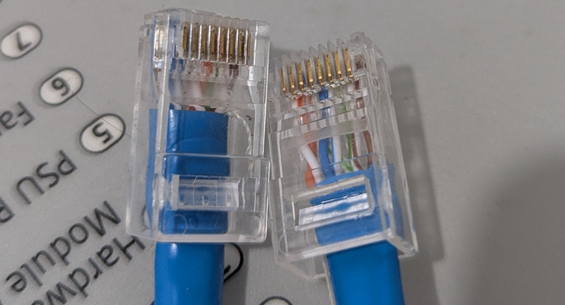 PRI RJ-48 Crossover Cable (orange and green cross over)
If you have a crimping tool, it is quicker and easier to make a T1/E1 crossover cable than it is to buy one. Only two cable pairs are needed, transmit connects to receive of the same polarity. You could use the other two pairs for something else, but I just connected them straight through.
| Pin | Pin |
|---|---|
| 1: Transmit + | 4: Receive + |
| 2: Transmit - | 5: Receive - |
| 3 | 3 |
| 4: Receive + | 1: Transmit + |
| 5: Receive - | 2: Transmit - |
| 6 | 6 |
| 7 | 7 |
| 8 | 8 |
It pays to clearly tag your crossover cable, since it won’t work as an ethernet cable:
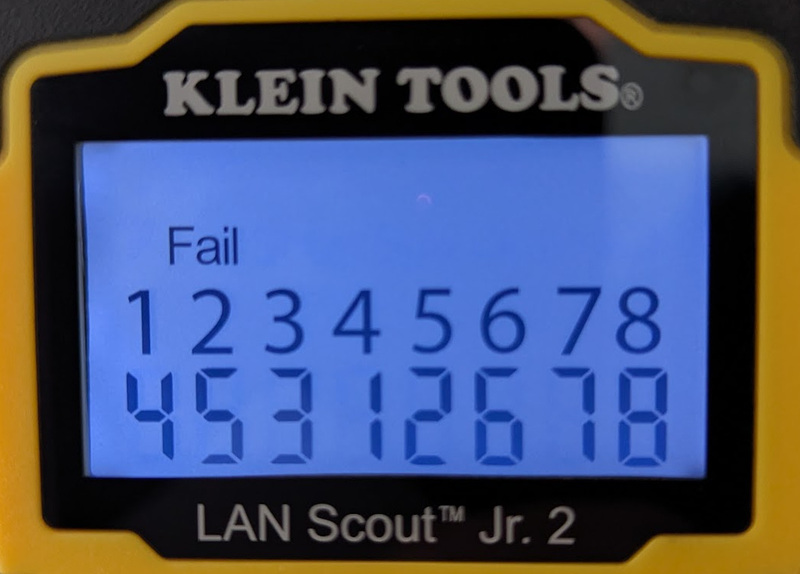 PRI RJ-48 Crossover Test Result
Initial 1921 (VWIC3-1MFT-T1/E1) Config
First, the card has to be configured for E1 and a channel group has to be created. A channel group reserves channels for a particular use (in this case data). For E1, each channel is 64kbps.
show inv shows that the card is in slot 0 subslot 0, which we use in the card and controller commands.
c1921(config)# card type e1 0 0
c1921(config)# controller E1 0/0/0
c1921(config-controller)# channel-group 0 timeslots 1-31
c1921(config-controller)# clock source internal
show int now shows a new serial interface. If we had split our channels into more channel groups we would have more serial interfaces, each reserving a portion of the E1 bandwidth:
Serial0/0/0:0 is down, line protocol is down
  Hardware is DSX1
  MTU 1500 bytes, BW 1984 Kbit/sec, DLY 20000 usec,
     reliability 255/255, txload 1/255, rxload 1/255
  Encapsulation HDLC, crc 16, loopback not set
Let’s configure the new serial interface as an X.25 DCE.
c1921(config)# interface Serial0/0/0:0
c1921(config-if)# bandwidth 1948
c1921(config-if)# encapsulation x25 dce
c1921(config-if)# x25 modulo 8
c1921(config-if)# x25 win 7
c1921(config-if)# x25 wout 7
c1921(config-if)# x25 ips 1024
c1921(config-if)# x25 ops 1024
Initial 3845 (VWIC2-1MFT-T1/E1) Config
show inv shows that the card is in slot 0 subslot 0, which we use in the card and controller commands.
c3845(config)# card type e1 0 0
c3845(config)# controller E1 0/0/0
c3845(config-controller)# channel-group 0 timeslots 1-31
c3845(config-controller)# clock source line
show int on the 3845 now shows the new serial interface:
Serial0/0/0:0 is up, line protocol is up
  Hardware is GT96K Serial
  MTU 1500 bytes, BW 1984 Kbit/sec, DLY 20000 usec,
     reliability 255/255, txload 1/255, rxload 1/255
  Encapsulation HDLC, loopback not set
Let’s configure the new serial interface as an X.25 DTE.
c3845(config)# interface Serial0/0/0:0
c3845(config-if)# shutdown
c3845(config-if)# bandwidth 1948
c3845(config-if)# encapsulation x25
c3845(config-if)# x25 modulo 8
c3845(config-if)# x25 win 7
c3845(config-if)# x25 wout 7
c3845(config-if)# x25 ips 1024
c3845(config-if)# x25 ops 1024
c3845(config-if)# no shutdown
Diagnostics
The 1921 has debug serial event enabled so when the controller was enabled on the 3845 it logged:
Apr  8 23:08:55.175: %CONTROLLER-5-UPDOWN: Controller E1 0/0/0, changed state to up
Apr  8 23:08:57.175: %LINK-3-UPDOWN: Interface Serial0/0/0:0, changed state to up
And it has debug x25 event enabled so when the serial interface was configured on the 3845 it logged:
Apr 8 23:21:42.254: Serial0/0/0:0: X.25 O R/Inactive Restart (5) 8 lci 0
Apr 8 23:21:42.254: Cause 7, Diag 0 (Network operational/No additional information)
Apr 8 23:21:42.254: Serial0/0/0:0: X.25 I R3 Restart (5) 8 lci 0
Apr 8 23:21:42.254: Cause 0, Diag 0 (DTE originated/No additional information)
Apr 8 23:21:43.254: %LINEPROTO-5-UPDOWN: Line protocol on Interface Serial0/0/0:0, changed state to up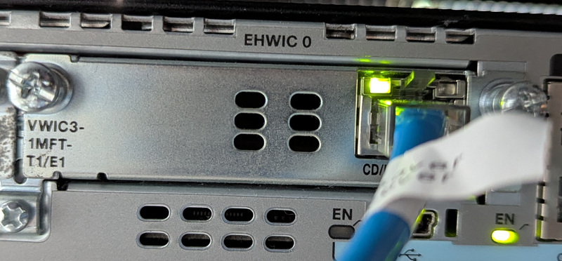 VWIC3-1MFT-T1/E1 in the 1921
The 1921 interface has changed to line protocol up and encapsulation X.25 (from HDLC):
Serial0/0/0:0 is up, line protocol is up
Hardware is DSX1
MTU 1500 bytes, BW 1948 Kbit/sec, DLY 20000 usec,
reliability 255/255, txload 1/255, rxload 1/255
Encapsulation X25, crc 16, loopback not set
Keepalive set (10 sec)
X.25 DCE, version 1984, address <none>, state R1, modulo 8, timer 0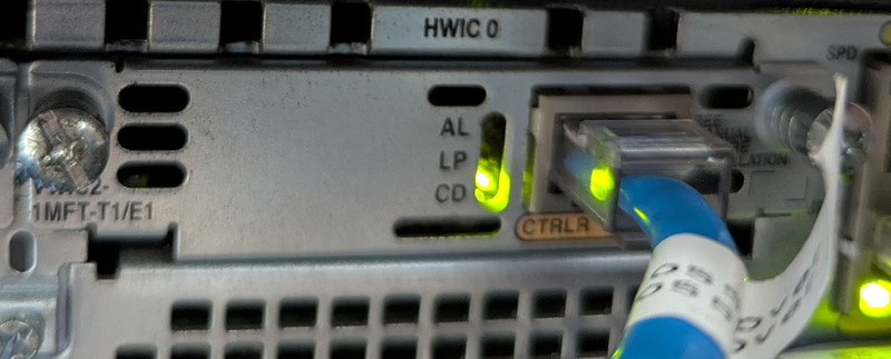 VWIC2-1MFT-T1/E1 in the 3845
The 3845 interface is also up:
Serial0/0/0:0 is up, line protocol is up
  Hardware is GT96K Serial
  MTU 1500 bytes, BW 1948 Kbit/sec, DLY 20000 usec,
     reliability 255/255, txload 1/255, rxload 1/255
  Encapsulation X25, loopback not set
  Keepalive set (10 sec)
  X.25 DTE, version 1984, address <none>, state R1, modulo 8, timer 0
Excellent, both ends can see the other.
Establish X.25 connectivity between the routers
I already have the following in my config on both ends, which enables XOT (X.25 over TCP) connections in to the routers:
x25 profile default dxe
 x25 address 702001
 x25 win 7
 x25 wout 7
 x25 ips 2048
 x25 ops 2048

x25 routing

line vty 5 30
 transport input pad
On IOS 15 we need to grant incoming XOT connections access, otherwise they are rejected:
xot access-group 10 profile default
access-list 10 permit any
From previous configuration, the 3845 is already using addresses in the 703… range and the 1921 is using addresses in the 701… range. I assign new addresses to the new serial interfaces.
c1921(config)# interface Serial0/0/0:0
c1921(config-if)# x25 address 701300
c1921(config-if)# exit
c1921(config)# x25 route 7033.* interface Serial0/0/0:0
c3845(config)# interface Serial0/0/0:0
c3845(config-if)# x25 address 703300
c3845(config-if)# exit
c3845(config)# x25 route 7013.* interface Serial0/0/0:0Test X.25 PAD connection from 1921 to 3845
To test connectivity I connect from the 1921 to the 3845 and vice versa using the pad command:
c1921#pad 703300
Trying 703300...Open

c3845.lan on line 711.

C i s c o  S y s t e m s
      ||        ||
      ||        ||
     ||||      ||||
 ..:||||||:..:||||||:..


User Access Verification

Username:
Password:


c3845>who
    Line       User       Host(s)              Idle       Location
*711 vty 5     admin      idle                 00:00:00 701300

  Interface    User               Mode         Idle     Peer Address
Which produced these debug logs:
Apr  8 23:43:54.114: Serial0/0/0:0: X.25 O R1 Call (15) 8 lci 1
Apr  8 23:43:54.114:   From (6): 701300 To (6): 703300
Apr  8 23:43:54.114:   Facilities: (0)
Apr  8 23:43:54.114:   Call User Data (4): 0x01000000 (pad)
Apr  8 23:43:54.118: Serial0/0/0:0: X.25 I R1 Call Confirm (3) 8 lci 1
Demonstrate X.25 over TCP (XOT) connectivity
Using xotpad I can now connect through the 1921 to the 3845 over XOT:
❯ ~/src/xotpad/target/debug/xotpad -g 192.0.2.247 -a 123456 703300 || stty sane
c3845.lan on line 711.

C i s c o  S y s t e m s
      ||        ||
      ||        ||             Cisco Systems, Inc.
     ||||      ||||            Network Services
 ..:||||||:..:||||||:..

User Access Verification

Username: x25
Password:

c3845>who
    Line       User       Host(s)              Idle       Location
*711 vty 5     x25        idle                 00:00:00 123456

  Interface    User               Mode         Idle     Peer Address
Demonstrate IP over X.25 connectivity
To test IP routing, I give each serial interface an IP address and a map to reach the other:
c1921(config)# interface Serial0/0/0:0
c1921(config-if)# ip address 192.0.2.1 255.255.255.252
c1921(config-if)# x25 map ip 192.0.2.2 703300 packetsize 1024 1024
c3845(config)# interface Serial0/0/0:0
c3845(config-if)# ip address 192.0.2.2 255.255.255.252
c3845(config-if)# x25 map ip 192.0.2.1 701300 packetsize 1024 1024On both ends, show ip route shows that routes have been created:
c1921#show ip route 192.0.2.2
Routing entry for 192.0.2.0/30
  Known via "connected", distance 0, metric 0 (connected, via interface)
  Routing Descriptor Blocks:
  * directly connected, via Serial0/0/0:0
      Route metric is 0, traffic share count is 1
The routers can ping each other:
c1921#ping 192.0.2.2
Type escape sequence to abort.
Sending 5, 100-byte ICMP Echos to 192.0.2.2, timeout is 2 seconds:
!!!!!
Success rate is 100 percent (5/5), round-trip min/avg/max = 1/2/4 ms
Which establishes an X.25 call:
Apr  8 23:52:39.726: Serial0/0/0:0: X.25 O R1 Call (18) 8 lci 2
Apr  8 23:52:39.726:   From (6): 701300 To (6): 703300
Apr  8 23:52:39.726:   Facilities: (3)
Apr  8 23:52:39.726:     Packet sizes: 1024 1024
Apr  8 23:52:39.726:   Call User Data (4): 0xCC000000 (ip)
Apr  8 23:52:39.730: Serial0/0/0:0: X.25 I R1 Call Confirm (3) 8 lci 2
Summary
The interface config looks like this on the 1921:
card type e1 0 0

controller E1 0/0/0
 clock source internal
 channel-group 0 timeslots 1-31

interface Serial0/0/0:0
 bandwidth 1948
 ip address 192.0.2.1 255.255.255.252
 encapsulation x25 dce
 x25 address 701300
 x25 win 7
 x25 wout 7
 x25 ips 1024
 x25 ops 1024
 x25 map ip 192.0.2.2 703300 packetsize 1024 1024

x25 route 7033.* interface Serial0/0/0:0
And this on the 3845:
card type e1 0 0

controller E1 0/0/0
 channel-group 0 timeslots 1-31

interface Serial0/0/0:0
 bandwidth 1948
 ip address 192.0.2.2 255.255.255.252
 encapsulation x25
 x25 address 703300
 x25 win 7
 x25 wout 7
 x25 ips 1024
 x25 ops 1024
 x25 map ip 192.0.2.1 701300 packetsize 1024 1024
At this point, we have successfully:
- Connected two routers back to back over T1/E1.
- Established X.25 connectivity between them.
- Demonstrated X.25 over TCP (XOT) connectivity.
- Demonstrated IP over X.25 connectivity.
You might also be interested in Serial and Smart Serial Back to Back.